
- Butt welding fittings
- bends
- T- X- Y- pieces
- T- and Y-bends
- reducers
- caps and heads
- collars
- branch saddles
- orbital fittings
- ANSI / ASME
- Industrial valves
- ball valves
- actuators
- drain cocks
- gate valves
- globe valves
- non-return valves
- Y-strainers
- control technology
- Flanges
- welding neck flanges
- threaded flanges
- blind flanges
- plate flanges
- loose plate flanges
- collars
- flange-fittings
- ANSI/ ASME
- other
- Systems
- TEEKAY
- Victaulic
- press fittings
- quick couplings
- clamp connections
- cutting rings
- DIN 11864/ DIN 11853
- railing construction
- Beverage fittings
- unions
- fittings
- pipe clamps
- Tri-Clamp
- valves & cocks
- flange connections
- inspection glasses
- filter & strainers
- spray balls

Teekay Axilock pipe couplingTA.
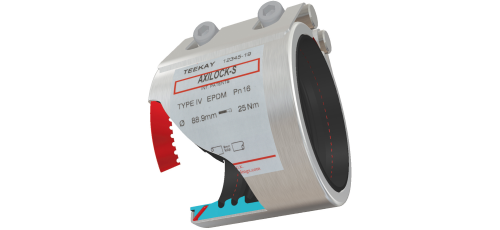


Teekay Axilock pipe coupling - axially restrained -
Teekay Axilock
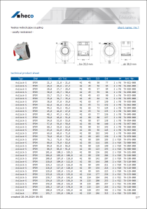
The Axilock is a axially restrained coupling with two metallic anchor rings, which engage
in the pipe surface when installed. The teeth of the anchor rings are pressed in the pipe
surface and thus prevent a pulling apart of the two pipes both under pressure and under
tensile loads.
The multi-chamber seal compresses itself on the pipe and thus protects the anchor ring
as well as the location of the pipe, on which the anchor ring engages in the surface,
of possible corrosion.
Dimension range
The listed dimensions are guides to the most common sizes. Couplings of other diameters can
also be made.
Housing design
| Model | Housing | Dimension range |
|---|---|---|
| Axilock | double | 141 - 711 mm |
| Axilock-S | single | 21,3 - 170 mm |
Material selection
| Type | Housing | Seal |
|---|---|---|
| Type I | AISI 304/ 1.4301 | Carbon-steel, PTFE coated |
| Type IV | AISI 316L/ 1.4404 | AISI 316/ 316L |
Temperature range
| Sealing material | Temperature range |
|---|---|
| EPDM | -40°C to +100°C |
| NBR | -20°C to +80°C |
| HNBR | -20°C to +150°C |
| FKM | -20°C to +1800°C |
| Silicone | -70°C to +200°C |
| Silicone-steam | -70°C ot +260°C |
Operating pressure
The specified operating pressures are designed for steel pipes. The minimum wall thickness
please refer to DIN 86128 Part I and II.
The strength calculation in the industrial sector is 1.5 times and in the ship area 4 times of the
operating pressure as a safety reserve.
| Dimension range | Type/ Version | Industry | Shipbuilding |
|---|---|---|---|
| 21,3 mm - 139,7 mm | Axilock S | 42 bar | 16 bar |
| 144,0 mm - 170,0 mm | Axilock-S | 34 bar | 13 bar |
| 141,3 mm - 222,0 mm | Axilock | 42 bar | 16 bar |
| 244,5 mm - 273,0 mm | Axilock | 23 bar | 8,75 bar |
| 323,9 mm - 326,0 mm | Axilock | 19 bar | 7,5 bar |
| 355,6 mm - 406,4 mm | Axilock | 15 bar | 6,0 bar |
| 429,0 mm | Axilock | 15 bar | 5,0 bar |
| 457,2 mm - 558,8 mm | Axilock | 2,5 bar | - |
| 609,6 mm - 711,2 mm | Axilock | 1,5 bar | - |
Distance between pipe ends
For axially restrained couplings the optimal distance between the pipe ends is 3-8 mm.
Max. angular deviation
| Pipe-OØ (in mm) | Angular deviation |
|---|---|
| 21,3 - 60,3 | 5° |
| 60,3 - 219,1 | 4° |
| 219,1 - 406,4 | 2° |
| 406,4 - 711,2 | 1° |
Permissible tolerances of the pipe outer diameter
| Pipe-OØ (in mm) | Tolerances |
|---|---|
| 21,3 - 35,0 | -0,3/ +0,3 |
| 38,0 - 57,0 | -1/ +1 |
| 60,3 - 429,0 | -1/ +2 |
| 429,0 - 711,2 | -1/ +2 |
Torques
Axilock-S
| Pipe-OØ | Screw size | Screw head* | Torque |
|---|---|---|---|
| 38,0 | M8 | 6 mm | 15 Nm |
| 42,4 | M8 | 6 mm | 15 Nm |
| 44,5 | M8 | 6 mm | 15 Nm |
| 48,3 | M8 | 6 mm | 15 Nm |
| 57,0 | M8 | 6 mm | 15 Nm |
| 60,3 | M8 | 6 mm | 15 Nm |
| 63,0 | M8 | 6 mm | 15 Nm |
| 70,0 | M8 | 6 mm | 15 Nm |
| 73,0 | M8 | 6 mm | 15 Nm |
| 76,1 | M8 | 6 mm | 20 Nm |
| 82,5 | M8 | 6 mm | 20 Nm |
| 88,9 | M8 | 6 mm | 20 Nm |
| 98,0 | M8 | 6 mm | 25 Nm |
| 101,6 | M8 | 6 mm | 25 Nm |
| 108,0 | M8 | 6 mm | 25 Nm |
| 110,0 | M8 | 6 mm | 25 Nm |
| 114,3 | M8 | 6 mm | 30 Nm |
| 118,0 | M8 | 6 mm | 30 Nm |
| 120,7 | M8 | 6 mm | 30 Nm |
| 127,0 | M8 | 6 mm | 30 Nm |
| 133,0 | M12 | 10 mm | 35 Nm |
| 139,7 | M12 | 10 mm | 35 Nm |
| 141,3 | M12 | 10 mm | 35 Nm |
| 144,0 | M12 | 10 mm | 35 Nm |
| 159,0 | M12 | 10 mm | 50 Nm |
| 165,0 | M12 | 10 mm | 50 Nm |
| 168,3 | M12 | 10 mm | 50 Nm |
| 170,0 | M12 | 10 mm | 50 Nm |
Axilock
| Pipe-OØ | Screw size | Screw head* | Torque |
|---|---|---|---|
| 141,3 | M12 | 10 mm | 65 Nm |
| 144,0 | M12 | 10 mm | 65 Nm |
| 154,0 | M12 | 10 mm | 65 Nm |
| 159,0 | M12 | 10 mm | 85 Nm |
| 165,0 | M12 | 10 mm | 85 Nm |
| 168,3 | M12 | 10 mm | 85 Nm |
| 170,0 | M12 | 10 mm | 85 Nm |
| 193,7 | M16 | 14 mm | 90 Nm |
| 219,1 | M16 | 14 mm | 100 Nm |
| 222,0 | M16 | 14 mm | 100 Nm |
| 244,5 | M16 | 14 mm | 100 Nm |
| 267,0 | M16 | 14 mm | 100 Nm |
| 273,0 | M16 | 14 mm | 110 Nm |
| 323,9 | M16 | 14 mm | 110 Nm |
| 326,0 | M16 | 14 mm | 110 Nm |
| 355,6 | M16 | 14 mm | 120 Nm |
| 378,0 | M16 | 14 mm | 110 Nm |
| 406,4 | M16 | 14 mm | 140 Nm |
* female square
For all couplings, the torque is noted on the housing label.
extended product description
Stainless steel TEEKAY Axilock
Teekay Axilock pipe couplingTA.

Teekay Axilock
The Axilock is a axially restrained coupling with two metallic anchor rings, which engage
in the pipe surface when installed. The teeth of the anchor rings are pressed in the pipe
surface and thus prevent a pulling apart of the two pipes both under pressure and under
tensile loads.
The multi-chamber seal compresses itself on the pipe and thus protects the anchor ring
as well as the location of the pipe, on which the anchor ring engages in the surface,
of possible corrosion.
Dimension range
The listed dimensions are guides to the most common sizes. Couplings of other diameters can
also be made.
Housing design
| Model | Housing | Dimension range |
|---|---|---|
| Axilock | double | 141 - 711 mm |
| Axilock-S | single | 21,3 - 170 mm |
Material selection
| Type | Housing | Seal |
|---|---|---|
| Type I | AISI 304/ 1.4301 | Carbon-steel, PTFE coated |
| Type IV | AISI 316L/ 1.4404 | AISI 316/ 316L |
Temperature range
| Sealing material | Temperature range |
|---|---|
| EPDM | -40°C to +100°C |
| NBR | -20°C to +80°C |
| HNBR | -20°C to +150°C |
| FKM | -20°C to +1800°C |
| Silicone | -70°C to +200°C |
| Silicone-steam | -70°C ot +260°C |
Operating pressure
The specified operating pressures are designed for steel pipes. The minimum wall thickness
please refer to DIN 86128 Part I and II.
The strength calculation in the industrial sector is 1.5 times and in the ship area 4 times of the
operating pressure as a safety reserve.
| Dimension range | Type/ Version | Industry | Shipbuilding |
|---|---|---|---|
| 21,3 mm - 139,7 mm | Axilock S | 42 bar | 16 bar |
| 144,0 mm - 170,0 mm | Axilock-S | 34 bar | 13 bar |
| 141,3 mm - 222,0 mm | Axilock | 42 bar | 16 bar |
| 244,5 mm - 273,0 mm | Axilock | 23 bar | 8,75 bar |
| 323,9 mm - 326,0 mm | Axilock | 19 bar | 7,5 bar |
| 355,6 mm - 406,4 mm | Axilock | 15 bar | 6,0 bar |
| 429,0 mm | Axilock | 15 bar | 5,0 bar |
| 457,2 mm - 558,8 mm | Axilock | 2,5 bar | - |
| 609,6 mm - 711,2 mm | Axilock | 1,5 bar | - |
Distance between pipe ends
For axially restrained couplings the optimal distance between the pipe ends is 3-8 mm.
Max. angular deviation
| Pipe-OØ (in mm) | Angular deviation |
|---|---|
| 21,3 - 60,3 | 5° |
| 60,3 - 219,1 | 4° |
| 219,1 - 406,4 | 2° |
| 406,4 - 711,2 | 1° |
Permissible tolerances of the pipe outer diameter
| Pipe-OØ (in mm) | Tolerances |
|---|---|
| 21,3 - 35,0 | -0,3/ +0,3 |
| 38,0 - 57,0 | -1/ +1 |
| 60,3 - 429,0 | -1/ +2 |
| 429,0 - 711,2 | -1/ +2 |
Torques
Axilock-S
| Pipe-OØ | Screw size | Screw head* | Torque |
|---|---|---|---|
| 38,0 | M8 | 6 mm | 15 Nm |
| 42,4 | M8 | 6 mm | 15 Nm |
| 44,5 | M8 | 6 mm | 15 Nm |
| 48,3 | M8 | 6 mm | 15 Nm |
| 57,0 | M8 | 6 mm | 15 Nm |
| 60,3 | M8 | 6 mm | 15 Nm |
| 63,0 | M8 | 6 mm | 15 Nm |
| 70,0 | M8 | 6 mm | 15 Nm |
| 73,0 | M8 | 6 mm | 15 Nm |
| 76,1 | M8 | 6 mm | 20 Nm |
| 82,5 | M8 | 6 mm | 20 Nm |
| 88,9 | M8 | 6 mm | 20 Nm |
| 98,0 | M8 | 6 mm | 25 Nm |
| 101,6 | M8 | 6 mm | 25 Nm |
| 108,0 | M8 | 6 mm | 25 Nm |
| 110,0 | M8 | 6 mm | 25 Nm |
| 114,3 | M8 | 6 mm | 30 Nm |
| 118,0 | M8 | 6 mm | 30 Nm |
| 120,7 | M8 | 6 mm | 30 Nm |
| 127,0 | M8 | 6 mm | 30 Nm |
| 133,0 | M12 | 10 mm | 35 Nm |
| 139,7 | M12 | 10 mm | 35 Nm |
| 141,3 | M12 | 10 mm | 35 Nm |
| 144,0 | M12 | 10 mm | 35 Nm |
| 159,0 | M12 | 10 mm | 50 Nm |
| 165,0 | M12 | 10 mm | 50 Nm |
| 168,3 | M12 | 10 mm | 50 Nm |
| 170,0 | M12 | 10 mm | 50 Nm |
Axilock
| Pipe-OØ | Screw size | Screw head* | Torque |
|---|---|---|---|
| 141,3 | M12 | 10 mm | 65 Nm |
| 144,0 | M12 | 10 mm | 65 Nm |
| 154,0 | M12 | 10 mm | 65 Nm |
| 159,0 | M12 | 10 mm | 85 Nm |
| 165,0 | M12 | 10 mm | 85 Nm |
| 168,3 | M12 | 10 mm | 85 Nm |
| 170,0 | M12 | 10 mm | 85 Nm |
| 193,7 | M16 | 14 mm | 90 Nm |
| 219,1 | M16 | 14 mm | 100 Nm |
| 222,0 | M16 | 14 mm | 100 Nm |
| 244,5 | M16 | 14 mm | 100 Nm |
| 267,0 | M16 | 14 mm | 100 Nm |
| 273,0 | M16 | 14 mm | 110 Nm |
| 323,9 | M16 | 14 mm | 110 Nm |
| 326,0 | M16 | 14 mm | 110 Nm |
| 355,6 | M16 | 14 mm | 120 Nm |
| 378,0 | M16 | 14 mm | 110 Nm |
| 406,4 | M16 | 14 mm | 140 Nm |
* female square
For all couplings, the torque is noted on the housing label.
This view is not optimized for mobile devices.
You can change back to desktop view.
This view is not optimized for mobile devices.
You can change back to desktop view.

